Windows getting started guide
Summary
This guide is for WindowMicrosoft serverWindows Server 2012 and above. This guide was speficicallyspecifically tested with Windows Server 2019, Windows Hyper-V serverServer 2022, and Windows Server 2022.
Introduction
This guide provides the recommended best practices for using the StorONE with Windows serverServer for iSCSi. This guide includes network best practices for physical data ports connecting to the S1, as well as basic troubleshooting steps.
Physical switch port recommendations
iSCSI network redundancy recommendations
iSCSI Networking Redundancy recommendations
For iSCSI networksnetworks, itStorONE isrecommends recommended to haveusing multiple network interfaces for each application host and StorONE array network interfacescontroller, dedicated forto iSCSI traffic. It is recommended that switchesSwitches for iSCSI data traffic should be connected via aan Inter Inter-Switch Link (ISL), or some equiliventequivalent manner to allow for proper networking and TCP connectivity. If you are using multiple subnets are used for iSCSI traffic, then each subnet will need tomust be contained within the appropriate switch and VLAN configuration.
iSCSINetwork interfaces used for iSCSI should not be part of any bond,bonded or Link Aggregaton.aggregated. iSCSI interfaces work best with Multipathingmultipathing IO software (MPIO) software to help aggregate paths loadpaths, balance load, and mitigate lost connections between application servers and StorONE array controllers.
StorONE recommends a minimum number of two interfaces per initiator server, along withand two iSCSI data connections per StorONE array controller. This allows for a total of four paths per controller for iSCSI data communication.
Spanning Tree
The second is a recommendation around switch ports when Spanning Tree Protocol (STP) is used in an environment. STP is responsible for ensuring that there are no network loops in a bridged network by selectively disabling network links and ensuring that there is only a single active path between any two network nodesnodes. If there are loops, thisLoops can havecause severe performance impactsissues onin your network with unnecessary forwardingpacket of packets taking place,forwarding, eventually leading to a saturated networknetwork.
StorONE recommends setting theall switch ports Connectingused toby storageinitiator portshosts and array controller hosts as either RSTP edge ports or Cisco portfast. This meansconfigures thatthe ports to immediately transition theirto the forwarding statestate, toskipping activethe listening and arelearning states that do not heldforward up by STP route calculations. traffic. This allows for the best possible transition for floating IP addresses during node failover.
JumboMTU
Frames(jumbo - large MTU
For iSCSI storage traffictraffic, viaStorONE iSCSIrecommends itincreasing isthe recommendedmaximum transmission unit (MTU) to increase9000, thecommonly referred to as jumbo frames. You must make MTU setting to 9000 MTU. This must be done onchanges the physical switch ports as well as the windowsWindows network adapters that are used for the iSCSi networks.
In the S1 TextTerminal User Interface (TUI) used for array setup, the ports configured for data trafficyou must also beconfigure instructedthe data interfaces to useset 9000the MTU to 9000:

Verify network settings
Interface Verification
To verify that the switch interfaces are correctly configured between the applicaitonapplication host and the StorONE storage arrayarray, weuse recommendthe usingping pingcommand from the windowsWindows CLI.command prompt or PowerShell. This will allow us to checkverifies basic network connectivity between the host and StorONE array, and also verifyverifies Jumbothe Framejumbo settingsframe settings.
FirstFirst, use averify basic pingconnectivity:
ping -S data.ip.from.host<source_data_interface_ip> StorONE.data.ip<destination_StorONE_interface_ip>If you do not see replies from the destination, identify and correct any network issues before continuing.
the basic command should return with a successful ping if not this will need to be resolved
To verify jumbo frames are working correctlycorrectly, use the following command:
ping -S host.data.ip<source_data_interface_ip> -f -l 8900 StorONE.data.ip<destination_StorONE_interface_ip>The -f flag sets the do-not-fragment (DF) bit, and the -l flag sets the packet length. If you see a response similar to Packet needs to be fragmented but DF set, then jumbo frames are not allowed somewhere in the path. Check the switch port configurations as well as the source and destination network interface settings.
Fibre Channel Hostinitiator hosts and Zoningzoning
For Fibre Channel (FC) networks or fabrics, itStorONE isrecommends recommended to haveusing multiple Host Bus Adapters (HBAs) for each application host and StorONE array controller Host Bus Adapters (HBAs)controller, dedicated forto FC traffic.
StorONE recommends a minimum number of two physical adapters per initiator server, along withand two FC data connectionsHBAs per StorONE array controller. This allows for a total of four paths per controller for FC data communication.
Multipath Multipathing softwareI/O (MPIO) software is required to manage the multiple paths to the iSCSIStorONE block volume. MPIO provides a mechanism for managing multiple paths to storage, including load balancing and failover behavior.
Aliases: StorONE recommends creating aliases for all host and StorONE Port World Wide NamessNames (pWWNs) to facilitate easy zone creation and tracking from the nameserver. Node World Wide Names (NWWNs) should not be used when zoning with or two the StorONE array.
Zoning: StorONE recommends no more than one HOST initiator pWWN per zone and no more than one array controller per zone. For each host initiator pWWN, there should be at least two zones per fabric connecting the StorONE array to the host.
A Minimum zoning example for a StorONE HA cluster:
| Fabric A |
Zone 1 A |
Fabric B |
Zone 1 B |
| Initiator |
Host initiator pWWN A |
Initiator |
Host Initiator pWWN B |
| Target |
StorONE Controller 1 pWWN A |
Target | StorONE Controller 1 pWWN B |
| Target |
StorONE Controller 2 pWWN A |
Target | StorONE Controller 2 pWWN B |
SMB network redundancy
SMB Networking Redundancy recommendations
For SMB networks it is recommended to have multiple network adapters dedicated for SMB traffic. StorONE recommends using Link Aggregation Control Protocol (LACP) for interface bonding and redundancy. LACP allows for one or more physical interfaces to be aggregated together for combined throughput, and at the same time can suffer the loss of one or more links of the interface group without a total loss of connectivity to the array.
StorONE recommends an HA pair of arrays if all SMB connections are lost between the NAS server and host application servers the array will perform a failover to transition the file services to the other node in the HA cluster.
Spanning Tree
Spanning Tree Protocol (STP) is responsible for ensuring that there are no network loops in a bridged network by disabling network links and ensuring that there is only a single active path between any two network nodes If there are loops, this can have severe performance impacts on your network with unnecessary forwarding of packets taking place, eventually leading to a saturated network
StorONE recommends setting the switch ports connecting to StorONE storage ports as either RSTP edge ports or Cisco portfast. This means that ports immediately transition their forwarding state to active and are not held up by STP route calculations. This allows for the best possible transition for floating IP addresses during node failover.
JumboMTU Frames(jumbo - large MTU
frames)
For storage traffic it is recommended to increase the MTU setting to 9000 MTU. This must be done on the physical switch ports as well as the windows network adapters that are used for the SMB networks.
In the S1 Text User Interface (TUI) used for array setup, the ports configured for data traffic must also be instructed to use 9000 MTU
MTU
InterfaceVerify Verification
network settings
To verify that the switch interfaces are correctly configured between the applicaitonapplication host and the StorONE storage arrayarray, weuse recommendthe usingping pingcommand from the windowsWindows CLI.command prompt or PowerShell. This will allow us to checkverifies basic network connectivity between the host and StorONE array, and also verifyverifies Jumbothe Framejumbo settingsframe settings.
FirstFirst, use averify basic pingconnectivity:
ping -S data.ip.from.host<source_data_interface_ip> StorONE.data.ip<destination_StorONE_interface_ip>theIf basicyou command should return with a successful ping ifdo not thissee willreplies needfrom tothe bedestination, resolvedidentify and correct any network issues before continuing.
To verify jumbo frames are working correctlycorrectly, use the following command:
ping -S host.data.ip<source_data_interface_ip> -f -l 8900 StorONE.data.ip<destination_StorONE_interface_ip>The
Multipath-IO-f flag sets the do-not-fragment (DF) bit, and the -l flag sets the packet length. If you see a response similar to Packet needs to be fragmented but DF set, then jumbo frames are not allowed somewhere in the path. Check the switch port configurations as well as the source and destination network interface settings.
Multipath I/O (MPIO) Installationinstallation (iSCSI and FC only)
To install Windows MPIOMPIO:
1)
Open
2) addAdd Roles and Features
3) the MultiPath I/O from the features list
list: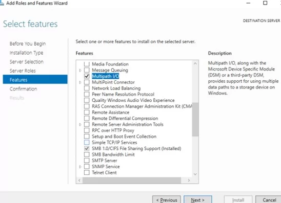
4) server
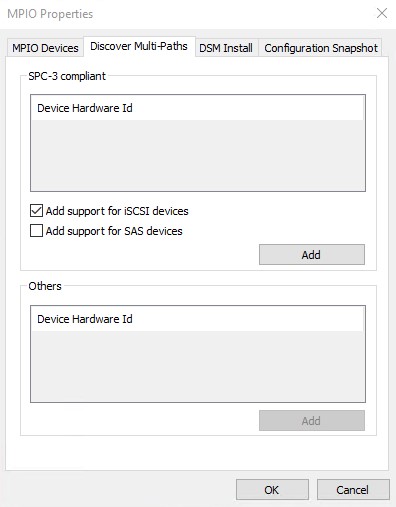
5)Openthe reboot completes, open Server Manager -, select Tools, and then MPIO.
6)only):
7) tabtab, and then check the addAdd support for iSCSI devices checkbox and click Add
:
Joining the StorONE array to an ADActive Directory (AD) domain
If you plan to use AD to control share access to the StorONE shares, we recommend joining the array to the Active Directory (AD) domain. The table below contains the port requirements for using Active Directory and Lightweight Driectory Access Protocol (LDAP)
Requirements:
- A dedicated floating IP address for file based traffic must be created on the StorONE array, this can be done via the array CLI or UI. This should be different than object or replication floating IP addresses.
- A NAS server must be created on the StorONE array using the dedicated floating IP for file based traffic.
- An administrator or domain administrator username and password to
joingjoin the domain. This is a one time use to create the computer account for the StorONE NAS server in the domain controller, and the credentials are not cached or otherwise retained by the array. - Forward and reverse DNS records must be in place for the AD domain controller, DNS servers, and the StorONE array controllers.
- Port requirements - The following ports need to be available for a successful AD
join.join:
| Port |
Inbound |
Outbound |
Location |
Useage |
| 53 |
YES |
YES |
DNS server |
DNS |
| 53 |
YES |
YES |
Array controller maagement IP Addresses |
DNS |
| 88 |
YES |
YES |
Domain Controller(s) |
Kerberos |
| 88 |
YES |
YES |
Array controller management IP addresses |
Kerberos |
| 123 |
YES |
YES |
Domain Controller, NTP server for Array controllers |
NTP |
| 123 |
YES |
YES |
Array Controller management IP addresses |
NTP |
| 389 |
YES |
YES |
Domain Controller(s) |
LDAP / AD |
| 389 |
YES |
YES |
Array controller management IP addresses |
LDAP / AD |
Creating a NAS server and Floating IP
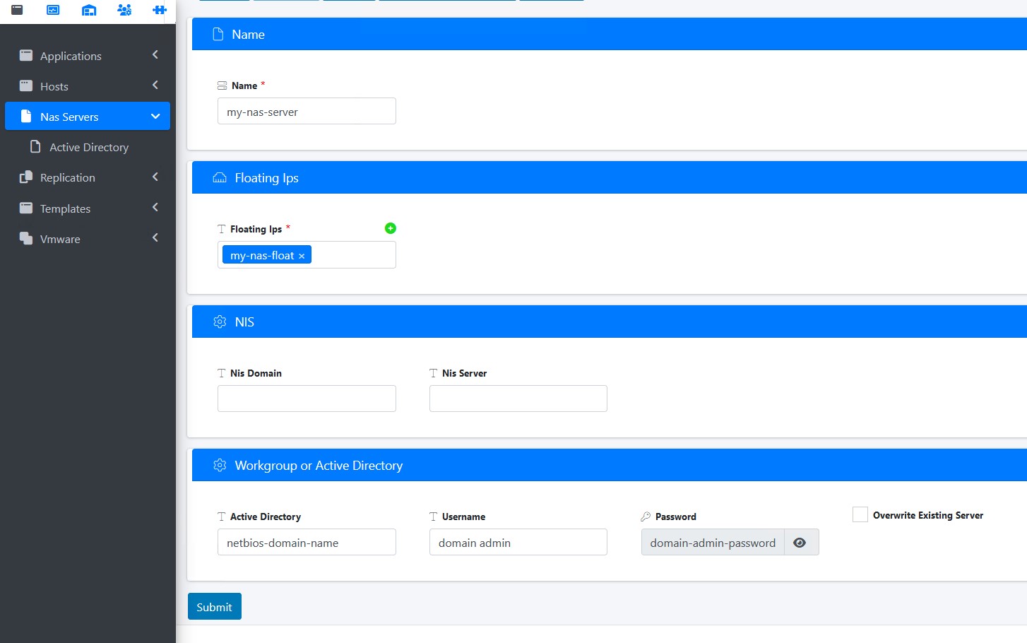
To create a NAS server and floating IP from the StorONE array GUI:
- Log into the array
- Select Applications and then Nas Servers
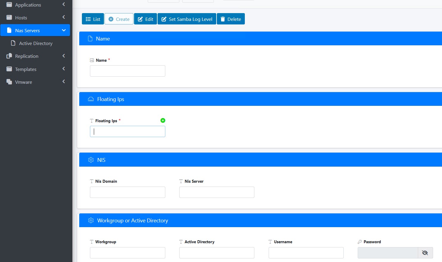
- Provide a name for your NAS server (it is recommended to keep the name less than 15 characters)
- Click on the "+" sign for Floating IPs. Enter the IP information for your Floating IP address and subnet, and make sure the correct DATA interface is selected for each Array controller in the cluster. Click Create
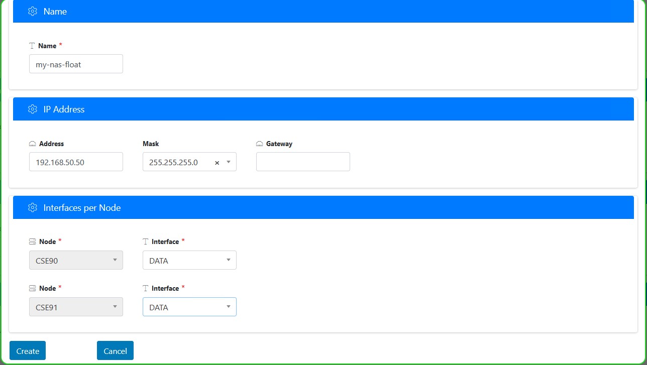
- Make sure the floating IP created is now used for the NAS server. Then enter the correct Net Bios or short domain name, and a username and password for a Domain admin then click Submit.


Setting Permissions for a StorONE SMB share as a Network Drive
To map a StorONE shared SMB volume tp a windows host. For a simple SMB connection a user will need to be configured on the array and allowed access to the StorONE SMB share. For AD credentials the StorONE array will need to be joined to the AD domain first and AD users will need to be added to the share.
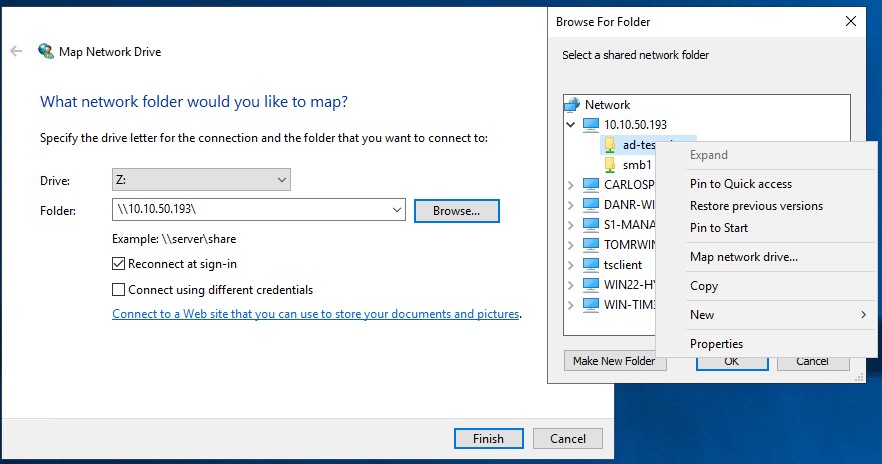
- Open "This PC" select the computer tab and then select "Map network drive"
- Select an available drive letter for the share to be mapped to on this server.
- For the first time connecting to the share, enter the floating IP for your StorONE and click the browse button
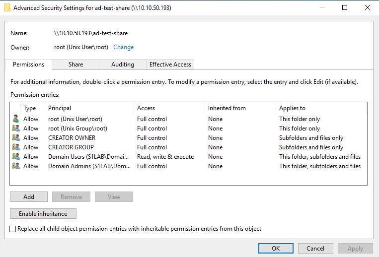
- Select the share from the StorONE floating IP right click and select Properties

- Select the "Security" Tab then click Advanced
- From the Permissions tab click Add

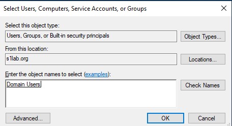
- CLick the link for "Select a principal" and enter your ad group and "check names" to verify. Repeat entering names and selecting "Check Names" until all AD groups are entered
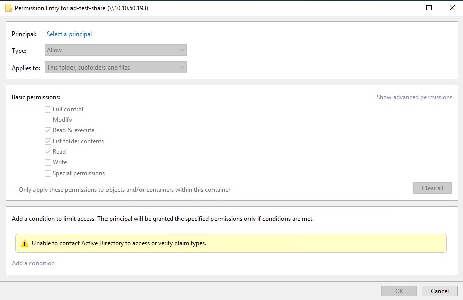

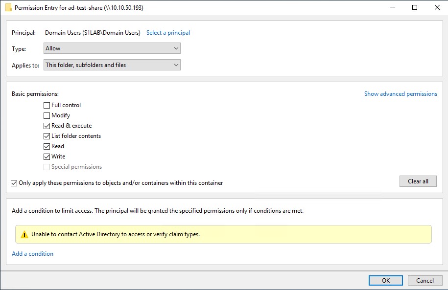
- To set permissions for each added AD group on the share, from the Permissions tab select the group and click Edit, then set the desired permissions for that group. Repeat for each group added as needed.

- These steps can be repeated as needed for additional shares from the StorONE array.
- For creating folders and subfolders within the share, the permissions can be set directly from the folders and subfolders as desired.

Mapping a StorONE SMB share as a Network Drive
To map a StorONE shared SMB volume tp a windows host. For a simple SMB connection a user will need to be configured on the array and allowed access to the StorONE SMB share. For AD credentials the StorONE array will need to be joined to the AD domain first and AD users will need to be added to the share.
- Open "This PC" select the computer tab and then select "Map network drive"
- Select an available drive letter for the share to be mapped to on this server.
- For the first time connecting to the share, enter the floating IP for your StorONE and click the browse button.
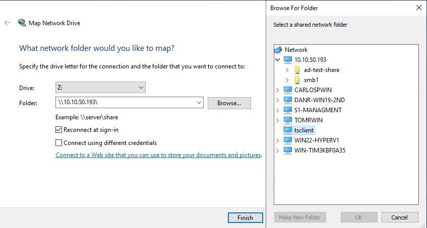

Click finish to complete maping the share as a network drive with your AD credentials.
NOTE: If different credentials are needed to connect to the share, check that box and then click Finish to provide those credentials