Windows getting started guide
Summary
This guide is for Window server 2012 and above. NotThis allguide recommendationswas have beenspeficically tested inwith allWindows versions,Server but2019, shouldWindows haveHyper-V similarserver functionality2022, acrossand versions.Windows Server 2022.
Introduction
This guide provides the recommended best practices for using the StorONE with Windows server for iSCSi. This guide includes network best practices for physical data ports connecting to the S1, as basic troubleshooting steps.
Physical switch port recommendations
iSCSI Networking Redundancy recommendations
For iSCSI networks it is recommended to have multiple application host and StorONE array network adaptersinterfaces dedicated for iSCSI traffic. It is recommended that switches for iSCSI data traffic should be connected via a Inter Switch Link (ISL), or some equilivent manner to allow for proper networking and TCP connectivity. If multiple subnets are used for iSCSI traffic, then each subnet will need to be contained within the appropriate switch and VLAN configuration.
iSCSI interfaces should not be part of any bond, or Link Aggregaton. iSCSI interfaces work best with Multipathing IO software (MPIO) to help aggregate paths load balance and mitigate lost connections between application servers and StorONE array controllers.
StorONE recommends a minimum number of two physical adaptersinterfaces per server, along with two iSCSI data connections per StorONE array controller. This allows for a total of four paths per controller for iSCSI data communication. Multipathing software (MPIO) is required to manage the multiple paths to the iSCSI volume. MPIO provides a mechanism for managing multiple paths to storage, including load balancing and failover behavior.
Spanning Tree
The second is a recommendation around switch ports when Spanning Tree Protocol (STP) is used in an environment. STP is responsible for ensuring that there are no network loops in a bridged network by disabling network links and ensuring that there is only a single active path between any two network nodes If there are loops, this can have severe performance impacts on your network with unnecessary forwarding of packets taking place, eventually leading to a saturated network
StorONE recommends setting the switch ports Connecting to storage ports as either RSTP edge ports or Cisco portfast. This means that ports immediately transition their forwarding state to active and are not held up by STP route calculations. This allows for the best possible transition for floating IP addresses during node failover.
Jumbo Frames - large MTU
For storage traffic via iSCSI it is recommended to increase the MTU setting to 9000 MTU. This must be done on the physical switch ports as well as the windows network adapters that are used for the iSCSi networks.
In the S1 Text User Interface (TUI) used for array setup, the ports configured for data traffic must also be instructed to use 9000
MTU

Fibre Channel Host and Zoning
For Fibre Channel (FC) networks or fabrics, it is recommended to have multiple application host and StorONE array controller Host Bus Adapters (HBAs) dedicated for FC traffic.
StorONE recommends a minimum number of two physical adapters per server, along with two FC data connections per array controller. This allows for a total of four paths per controller for FC data communication. Multipathing software (MPIO) is required to manage the multiple paths to the iSCSI volume. MPIO provides a mechanism for managing multiple paths to storage, including load balancing and failover behavior.
Aliases: StorONE recommends creating aliases for all host and StorONE Port World Wide Namess (pWWNs) to facilitate easy zone creation and tracking from the nameserver. Node World Wide Names (NWWNs) should not be used when zoning with or two the StorONE array.
Zoning: StorONE recommends no more than one HOST initiator pWWN per zone and no more than one array controller per zone. For each host initiator pWWN, there should be at least two zones per fabric connecting the StorONE array to the host.
A Minimum zoning example for a StorONE HA cluster:
| Fabric A |
Zone 1 A |
Fabric B |
Zone 1 B |
| Initiator |
Host initiator pWWN A |
Initiator |
Host Initiator pWWN B |
| Target |
StorONE Controller 1 pWWN A |
Target | StorONE Controller 1 pWWN B |
| Target |
StorONE Controller 2 pWWN A |
Target | StorONE Controller 2 pWWN B |
SMB Networking Redundancy recommendations
For SMB networks it is recommended to have multiple network adapters dedicated for SMB traffic. StorONE recommends using Link Aggregation Control Protocol (LACP) for interface bonding and redundancy. LACP allows for one or more physical interfaces to be aggregated together for combined throughput, and at the same time can suffer the loss of one or more links of the interface group without a total loss of connectivity to the array.
StorONE recommends an HA pair of arrays if all SMB connections are lost between the NAS server and host application servers the array will perform a failover to transition the file services to the other node in the HA cluster.
Spanning Tree
Spanning Tree Protocol (STP) is responsible for ensuring that there are no network loops in a bridged network by disabling network links and ensuring that there is only a single active path between any two network nodes If there are loops, this can have severe performance impacts on your network with unnecessary forwarding of packets taking place, eventually leading to a saturated network
StorONE recommends setting the switch ports connecting to StorONE storage ports as either RSTP edge ports or Cisco portfast. This means that ports immediately transition their forwarding state to active and are not held up by STP route calculations. This allows for the best possible transition for floating IP addresses during node failover.
Jumbo Frames - large MTU
For storage traffic it is recommended to increase the MTU setting to 9000 MTU. This must be done on the physical switch ports as well as the windows network adapters that are used for the SMB networks.
In the S1 Text User Interface (TUI) used for array setup, the ports configured for data traffic must also be instructed to use 9000 MTU as shown below:
Windows Power Plan Setting
Ensure the windows power plan is set to High Performance as shown below.

In addition, confirm that the Power Management setting on the ethernet cards is disabled. This option is enabled by default in most server installations. Note this may look different with different Ethernet adapters.

Multipath-IO (MPIO)
Multipath-IO (MPIO) defines how the host distributes IOs across the available paths to the storage. There are several options available as shown below.
Fail Over Only (FOO) - This uses a single active path, and the rest of the paths are standby paths. The active path is used for sending all I/O. If the active path fails, then one of the standby paths is used. When the path that failed is reactivated or reconnected, the standby path that was activated returns to standby.
Round Robin (RR) – This is the preferred method of load balancing. This allows the Device Specific Module (DSM) to use all available paths for MPIO in a balanced way. This is the default option that is chosen when creating Multiple paths in Microsoft Server.
Least Queue Depth (LQD) – This is another load balancing option that sends I/O down the path with the fewest currently outstanding I/O requests.
Least Blocks (LB) - Load balancing policy that sends I/O down the path with the least number of data blocks currently being processed.
Which one should I use? The Round Robin (RR) policy distributes IOs evenly across all Active/Optimized paths and suitable for most environments. Least Queue Depth (LQD), is similar to RR in that IOs are distributed across all available Active/Optimized paths, however it may have some additional benefits. LQD will bias IOs towards paths that are servicing IO quicker (paths with lesser queues). In the event that one path becomes unstable or unavailable, LQD will prevent the utilization of that path reducing impact to the environment. Consider testing both options in your environment to see which performs better for your use case.
Windows MPIO Settings


iSCSI Troubleshooting
Problem: Can’t establish a connection to iSCSI target from Windows iSCSI initiator. This is the first time using iSCSI on this S1 deployment. What am I missing?
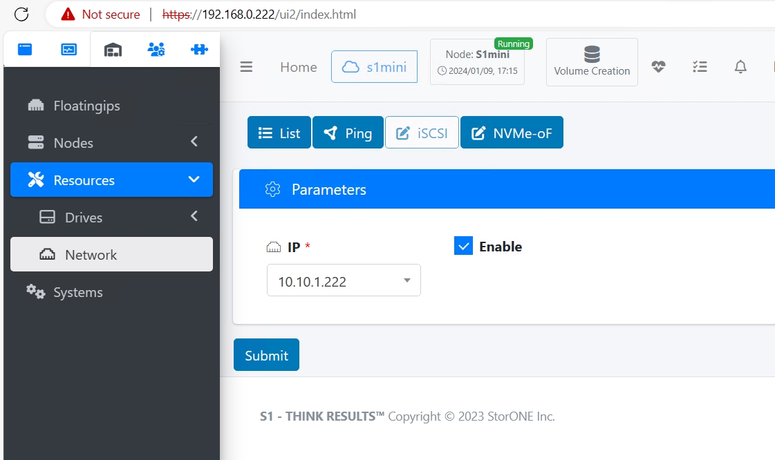
Solution: Ensure iSCSI is enabled on both (all) physical DATA interfaces within S1. This can be accomplished via the GUI or the CLI.
From the CLI, resources network iscsi --enable --ip ip_address_of_data_interface
Problem: Can’t login to iSCSI target.
Solution: Verify your host IQN is correct for your host entry in S1. This is located in the Configuration tab of iSCSI Initiator application on the Windows host.

Next, Verify the host is configured with the correct IQN and IP for the server you connecting to.
From the CLI, use the command : hosts list (hostname) --iqn --ip
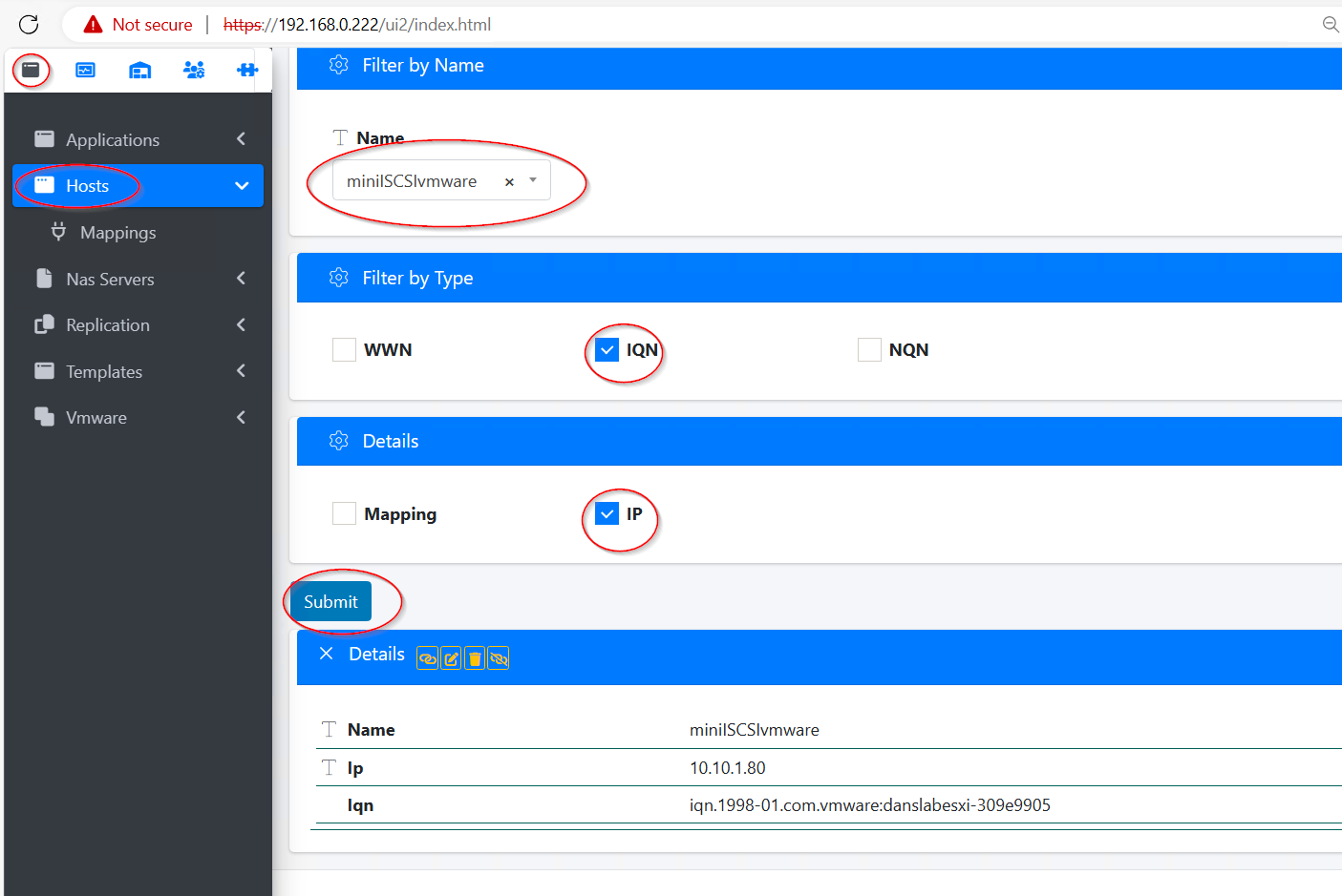
From the GUI, go to Applications Volumes, select hosts, select the host name in questions, check the box next to IQN and IP, then click Submit.